I. Datamax I-4212e Printer Settings
1.1 Printer Connection
1.1.1 Power Connection
Note: Before connecting the AC power cord or cable to the printer, ensure that the power switch is in the off position.

1.1.2 Interface Connection
This printer can be connected to the host via a parallel, USB, serial, or optional network interface. The printer will automatically connect to the first port that feeds valid data. Once a connection is established, the printer must be restarted before the interface connection can be changed.
1.2 Installing Label Paper
Follow these steps to load label paper into the printer:
1. Open the label paper cover. Turn and release the printhead locking lever to raise the printhead assembly.
2. Turn the label paper guide down.
3. Roll the label paper onto the label spool.
4. Guide the label paper out of the printer as shown in the diagram. Raise the label paper guide. Push the label paper guide inward to the edge of the label paper.
5. Close the printhead assembly and turn the printhead locking lever to the locked position.
6. Close the cover and press the paper feed button several times to feed the label paper to the correct position, ensuring it is correctly tracked.
If the top edge of each label is not detected correctly, the printer may need to be calibrated.
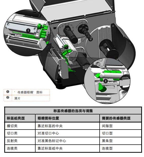
1.3 Label Sensor Adjustment
The label sensor position needs to be such that the printer can detect the presence of the label paper and the label header (except for continuous label paper, whose header is set via the front panel).
Adjustment steps:
1. Install the label paper, then grip the slider and move the sensor eye icon to the appropriate position above the label paper, as shown in the following figure:
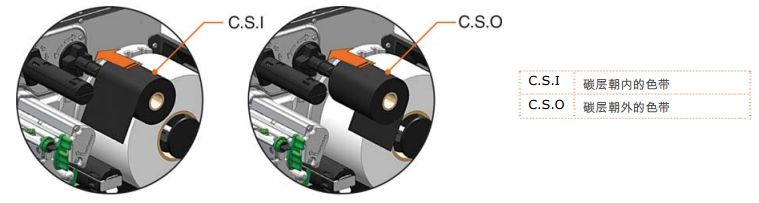
1.4 Installing the Ribbon A
ribbon is required for thermal transfer label paper. It is recommended that the ribbon width be slightly wider than the label paper being used. This printer can use either “internal carbon” or “external carbon” ribbons. The steps for installing the ribbon are as follows:
1. Open the label cover. Turn and release the printhead locking lever to raise the printhead assembly.
2. Attach the ribbon reel to the ribbon mounting shaft, placing it against the flange. Ensure the ribbon is unwound in the correct direction. The diagram below illustrates the correct ribbon installation direction.
3. Wrap the ribbon from under the ribbon roller to the front of the printer, then extend it approximately 12 inches.
4. Close the printhead assembly and turn the printhead locking lever to the locked position. Wind the ribbon upwards onto the ribbon take-up shaft, then turn clockwise several times to secure it in place.
5. Close the cover, then press the paper feed button several times to feed the ribbon to the appropriate position and ensure it is properly tracked.
1.5 OPTImedia
The OPTIMedia function is designed to reduce setup time when using Datamax-O’Neil brand label paper and ribbons. This function automatically adjusts the printer’s heat and speed to optimal levels for best print quality. By using the model prefixes of the label paper and ribbon (printed on the shipping box), users can quickly configure the printer to achieve the best print quality for a specific label paper and ribbon combination.
Steps to select OPTIMedia:
1. Press the MENU button.
2. Ensure “MEDIA SETTINGS” is highlighted, then press the ENTER button.
3. Ensure OPTImedia is highlighted, then press the ENTER button.
4. Use the down arrow key to scroll to the model prefix of the label paper being used, then press the ENTER button.
5. Thermal label paper: “OK” is displayed, then press the EXIT button to exit the menu system. Thermal transfer label paper
: The printer immediately prompts you to select the ribbon being used. Scroll to the model prefix of the ribbon being used, then press the ENTER button. “OK” is displayed, then press the EXIT button to exit the menu system.
The printer is now ready to print using the selected label paper/ribbon.
This method will not work if you are using non-Datamax-O’Neil brand supplies.
II. Datamax I-4212e Printer Operation
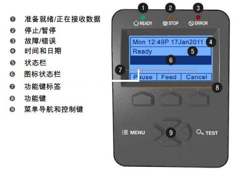
2.1 Front Panel
This control panel is an event-driven interface consisting of a graphical display and a keyboard. In addition to providing current printer information, the functions of items and buttons in the main display area can be changed in different modes according to the needs of operational events.
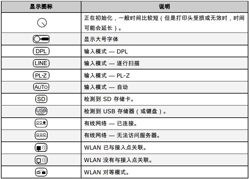
2.1.1 Display Icon
2.2 Windows Driver
Datamax I-4212e Driver Download: http://www.chongshang.com.cn/news/view.asp?id=441
Some important settings in the Windows driver require attention:
1. Page Setup tab: Stock
. The Stock setting needs to match the size of the label being used. If you cannot find a matching setting, click “New” and then enter the size of the label you are using.
2. Options tab: Print Speed and Printhead Temperature.
These two settings have the greatest impact on print quality. Some label papers require higher printing temperatures and slower printing speeds to ensure image print quality.
2.3 Label paper calibration
2.3.1 Quick Calibration
A quick calibration should generally be performed during label paper installation to optimize detection parameters.
Note: (1) This calibration is not always necessary when using continuous label paper. (2) If the gap between labels is large, the label paper may need to be changed before proceeding to the next step.
The steps to calibrate the printer are as follows:
1. Ensure the printer is turned on and idle (i.e., not offline), label paper is installed, the label sensor is adjusted, and the sensor type is selected.
2. Press and hold the paper feed button until at least one full label is output, then release the paper feed button and wait for the printer to process the data. There are two possible results:
If the calibration is successful, “CALIBRATION COMPLETE” will be displayed on the screen, and the label paper will feed to the beginning of the next label;
if the calibration is unsuccessful, “CALIBRATION FAILED” will be displayed on the screen. In this case, check the following prompts to help resolve the issue:
Calibration prompt:
“WARNING LOW BACKING” is usually displayed when calibrating die-cut label paper or cut label paper with highly transparent backing.
If the first attempt fails, press and hold the paper feed button until two labels are printed consecutively. However, if “CALIBRATION FAILED” appears again, perform the standard calibration routine.
2.3.2 Paper Out Calibration
Paper out calibration is used to calibrate the printer’s label sensor so that it can detect a “paper out” status. The calibration steps are as follows:
1. Ensure the printer is turned on and in an idle state (i.e., not offline), and that the label paper has been removed from the printer.
2. Press and hold the pause and paper feed buttons simultaneously. The printer will then complete the calibration and be able to detect a “paper out” status.
2.3.3 Standard Calibration
Standard calibration can be performed using the NETira CT utility or via the printer menu using the front panel buttons. Standard calibration provides dynamic readings, which are useful when there are small cuts or stripes on the label paper that are important for positioning. Three types of calibration samples are required:
No paper – no label paper on the sensor;
Gap, cut, or stripe – label backing, cut, or stripe placed on top of the sensor;
Paper – label (and backing, if present) placed on the sensor.
The steps to calibrate the label sensor are as follows:
1. Turn on the printer and wait for the initialization operation to complete and display READY.
2. Press the MENU button. Ensure that MEDIA SETTINGS is highlighted, and then press ENTER. Use the down arrow key to scroll to “SENSOR CALIBRATION”.
3. Press ENTER to enter “SENSOR CALIBRATION”. Use the down arrow key to scroll to “PERFORM CALIBRATION”. Press ENTER again, and then press YES to continue to the next step. Press NO to abort the process.
4. The screen displays “REMOVE LABEL STOCK/PRESS ESC KEY/yyy”. Remove the label paper. Press ESC if no label paper is installed. (yyy indicates the current sensor reading.)
5. Continue according to the label paper type:
◆ For die-cut labels, the screen displays “SCAN BACKING/PRESS ESC KEY/yyy”. Tear one or two labels from the backing and install the label paper. Place the label sensor under the backing area and press ESC.
◆ For cut/reflective labels, the screen displays “SCAN MARK/PRESS ESC KEY/yyy”. Install the label paper. Place the label sensor under the cut (or black stripe) and press ESC.
◆ For continuous labels, “REMOVE LABEL STOCK/PRESS ESC KEY/yyy”, press ESC, and then proceed to the next step.
6. Screen display: SCAN PAPER/PRESS ESC KEY/yyy. Continue execution according to the label paper type:
◆ For all label papers except continuous ones, place the label material (and backing, if any) above the sensor, and then press the ESC key.
◆ Continuous label paper—Install the label paper. Place the label sensor below the label paper and press the ESC key.
7. Observe the calibration result. The screen displays CALIBRATION COMPLETE, indicating successful calibration.
8. Press the ESC key, and then press EXIT to exit the ready state. When calibrating gap or reflective label paper, press and hold the “Paper Feed” key until at least one label is output.
2.3.4 Advanced Input Calibration
Advanced input calibration is an alternative calibration method for special label paper types. It uses different sampling algorithms to acquire sensor readings and selects the optimal algorithm from these readings, which is then manually entered into the database.
Note: Advanced input calibration should only be used after standard calibration has proven unsuccessful.
The steps to calibrate the label sensor are as follows:
1. Turn on the printer and wait for the initialization operation to complete and display READY.
2. Press the MENU button. Ensure MEDIA SETTINGS is highlighted, and then press ENTER. Use the down arrow key to scroll to “SENSOR CALIBRATION”.
3. Use the down arrow key to highlight “ADVANCED ENTRY”, and then press ENTER.
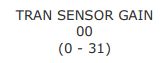
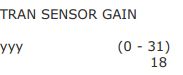
4. Scroll to “TRAN SENSOR GAIN” (or REFL SENSOR GAIN, if using reflective label paper), and then press ENTER.
5. Install the label paper. Place the label paper within the coverage area of the label sensor, then lower and lock the printhead assembly.
Note: Do not align the aperture with the label sensor; if using pre-printed label paper, ensure that the label area above the sensor is free of text, images, or lines.
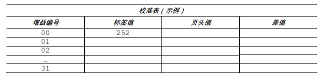
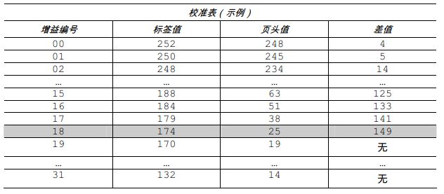
6. Use the up and down keys to set the gain number to 00. Record the sensor reading as the label value corresponding to gain number 00 in the table (32 rows x 4 columns, headers similar to the table below).
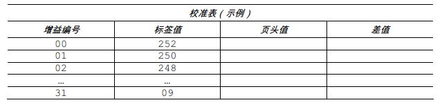
7. Use the up and down keys to increment the gain number by 1, and then record the label value. Repeat this process for each gain number.
8. Raise the printhead assembly, and then continue according to the label paper type:
◆ Die-cut label paper— Tear one or two labels from the backing and place the backing within the coverage area of the label sensor. Adjust the label sensor as needed.
◆ Cut label paper— Place the cut edge of the label paper within the coverage area of the label sensor.
◆ Reflective label paper— Place the black stripe of the label paper within the coverage area of the label sensor.
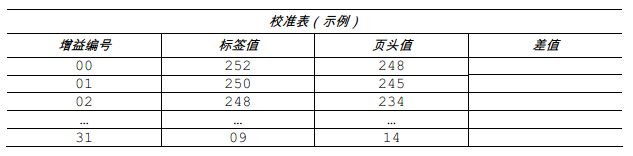
9. Lower and lock the printhead assembly. Use the up and down keys to set the gain number to 00. In the table, record this reading as the header (TOF) value corresponding to gain number 00.
10. Use these keys to increment the gain number by 1. Record the header value. Repeat this process for each gain number.
11. In the example calibration table, the label value and header value are at least 20. Subtract the two numbers and record the result as the difference (see below). Find the largest difference and its corresponding gain number. This gain number will be used to resample the label paper.
In this example, gain number 18 is selected because both readings are at least 20 and their difference is the largest.
12. Use these keys to set the gain number determined in the previous step. Press ENTER to enable the setting.
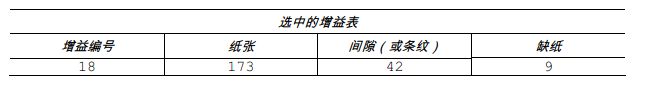
13. Fill in the table with the new measurement value (see the example below), as follows:
(A) Raise the printhead assembly. Place the label above the label sensor, then lower and lock the printhead assembly. Record the sensor reading as “Paper”.
(B) Raise the printhead assembly. Place the backing, notch, or stripe over the label sensor, then lower and lock the printhead assembly. Record the sensor reading as “Gap or Stripe”.
(C) Raise the printhead assembly. Remove all label paper from the label sensor, then lower and lock the printhead assembly. Record the sensor reading as “Paper Out”.
Note: Resampled values may differ from previously recorded values. This is normal; no readjustment of the label sensor is required.
14. Press the ESC key. Use these buttons to scroll to “PAPER SENSOR LEVEL” (or REFL PAPER LEVEL, if using reflective label paper), then press ENTER. Use these keys to set the paper value determined in step 13, then press ENTER.
15. Press the ESC key. Scroll to “GAP SENSOR LEVEL” (or MARK SENSOR LEVEL, if using reflective label paper), then press ENTER. Set the gap (or stripe) value determined in step 13, then press ENTER.
16. Press the ESC key. Scroll to “EMPTY SENSOR LEVEL” and press ENTER. Set the paper shortage value determined in step 13 and press ENTER.
17. Press the EXIT key, and then press “YES” when prompted in the “SAVE CHANGES” prompt box. The operation steps are complete, and the entire process is about to end.
18. Press and hold the “Feed” key until at least one label is printed. The printer is now ready.
Note: If the calibration attempt fails, reduce the sensor sensitivity as follows: Re-enter the ADVANCED MENU. Go to MEDIA SETTINGS/SENSOR CALIBRATION/ADVANCED ENTRY/TRAN (or REFL) SENSOR GAIN, and then decrease the corresponding gain setting in increments of 1. Exit the menu and save the changes. Test label paper with the new settings. Repeat if necessary until a usable gain setting is obtained.
III. Datamax I-4212e Printer System Menu
3.1 Overview of the Menu System
The menu system consists of three primary branches, each with different secondary menus or function access levels:
● User menu provides access to basic printer settings and functions;
● Advanced menu provides access to all operating settings, functions, and diagnostics;
● Test menu provides access to test, user-defined, and previous label printing functions.
Note: (1) A prompt may appear before granting menu access and changes take effect; see “Security” for details. (2) The display contrast is adjustable: Press and hold the MENU button to cycle through the contrast range (this may take several seconds), and release the button when the desired appearance is achieved.
3.2 User Menu
The user menu consists of the following basic options:
● Label Paper Settings
● Print Control
● Printer Options
● System Settings
Note: (1) Some setting changes will only take effect (and be saved) when “Save Changes” is prompted and “YES” is selected. (2) Label software may override printer menu settings in some cases; please refer to the Advanced Menu for details.
3.3 Advanced Menu
The Advanced Menu consists of all the settings, controls, and function options in the following menus:
● Label Paper Settings
● Print Controls
● Printer Options
● System Settings
● Communications
● Diagnostics
After selecting the Advanced Menu, simply press the MENU button to open it. The steps to enable the Advanced Menu are as follows:
1. Press the MENU button.
2. Use the up or down arrow keys to scroll to “SYSTEM SETTINGS” and then press ENTER.
3. Scroll to “MENU MODE” and then press ENTER.
4. Scroll to “ADVANCED MENU” and then press ENTER. (When finished, “OK” will be displayed on the screen, and the printer will exit the menu system.)
Note: (1) Some setting changes will only take effect (and be saved) when “Save Changes” is selected. (2) Label software may override printer menu settings in some cases; please refer to “Advanced Menu/Communications/Host Settings” to avoid potential conflicts. (3) To return to the user menu, select the menu again, or restore its factory default value.
3.4 Test Menu
The test menu consists of test options and information label options:
● Print Quality Label
● Print Configuration
● Ribbon Test Label
● Test Label
● Verification Label
● Print Previous Label
● User-defined Label
These labels are generated internally by the system and printed according to the pre-selected label paper type, print speed, and heat settings. These print settings can be changed via the menu system or host commands. Print the entire layout using full-width label paper; otherwise, adjust the printer and set the “Label Width” menu settings.
Note: (1) Press the CANCEL button to stop printing. (2) A print delay can be set; see “Print Test Speed” (Diagnostics section).
3.5 Menu Details
3.5.1 Label Paper Settings
The label paper settings menu includes label/ribbon detection and selection functions, as well as printhead cleaning options (items marked with an asterisk are only accessible through the advanced menu):
● OPTimedia
● Label Paper Type
● Label Paper Index Type
● Label Length
● Maximum Label Length*
● Out of Paper Distance*
● Label Width
● Ribbon Shortage Options*
● Sensor Calibration*
● Printhead Cleaning*
Menu options are defined on the following pages:
■ OPTimedia automatically configures various print settings based on the label paper/ribbon combination.
■ MEDIA TYPE: Selects the method used to print labels. This should be set according to the type of label paper used, where:
DIRECT THERMAL: Sets to use label paper that generates images through a heat reaction.
THERMAL TRANSFER: Sets to use label paper that requires a ribbon to generate images.
■ MEDIA INDEX TYPE: Selects the “To-the-Front” (TOF) detection method to determine the label’s guide edge, where:
GAP: Identifies the header by detecting gaps in the label paper. (Default Settings)
NOTCH: Identifies the header by detecting cuts in the label paper.
HOLE: Identifies the header by detecting holes in the label paper.
BLACK MARK: Identifies the header by detecting reflective (black) stripes on the bottom of the label paper.
CONTINUOUS: Does not use header identification; instead, it determines the header based on the label length (set in the label paper settings).
■ LABEL LENGTH: Determines the label length (0 – 99.99 in.) when “SENSOR TYPE” is set to “CONTINUOUS”, where:
04.00: Default setting.
■ MAXIMUM LABEL LENGTH: Sets the label paper length (0 – 99.99 in.) fed when the printer detects a header error before reporting it. In this case, “Sensor Type” is set to “GAP” or “REFLECTIVE”, where:
8.00: Default setting.
The maximum label length is typically 2.5 to 3 times the physical label length.
■ PAPER EMPTY DISTANCE: Sets the length of label paper the printer attempts to feed before reporting a paper out error (0 – 99.99 in.), where:
0.25: Default setting.
When using transparent or semi-transparent label paper, this setting should be greater than the actual label length.
■ LABEL WIDTH: Sets the maximum printable width. Content exceeding this setting will not be printed, where:
4.65: Default setting.
■ RIBBON LOW OPTIONS: Defines the printer’s response when the ribbon is running low when thermal transfer mode is selected, where:
RIBBON LOW DIAMETER: Sets the critical diameter of the ribbon roll (1.00 – 2.00 in.) that triggers the “Low Ribbon Warning” message, where: 0.50 is the default setting.
PAUSE ON RIBBON LOW: Enables the printer to pause when the “Insufficient Ribbon Diameter” condition is met. ENABLE: Pauses operation when the “Insufficient Ribbon Diameter” condition is detected; the PAUSE button must be pressed to continue printing. DISABLE: No operator intervention is required; printing continues even when a ribbon error is reported. (Default setting)
■ SENSOR CALIBRATION: Selects the label sensor calibration method.
PERFORM CALIBRATION: Sets these values through the printer’s internal calculations, as described in the “Standard Calibration” program.
ADVANCED ENTRY: Sets these values manually (typically used for label papers that are difficult to calibrate), as described in “Advanced Input Calibration.”
PAPER
SENSOR LEVEL: Sets a threshold value (0-255) for paper, with a default setting of 170.
REFL PAPER LEVEL: Sets a threshold value (0-255) for reflective label paper, with a default setting of 170.
GAP SENSOR LEVEL: Sets the threshold value (0-255) for gap labels, with a default value of 040.
MARK SENSOR LEVEL: Sets the threshold value (0-255) for striped labels, with a default value of 040.
EMPTY SENSOR LEVEL: Sets the threshold value (0-255) for paper shortages, with a default value of 000.
TRAN SENSOR GAIN: Sets the sensitivity (0-31) for transmissive sensors, with a default value of 15.
REFL SENSOR GAIN: Sets the sensitivity (0-31) for reflective sensors, with a default value of 15.
■ PRINTHEAD CLEANING: Controls automatic cleaning alarms and functions, including:
CLEAN HEAD SCHEDULE: Specifies the length of print (in inches or centimeters) required before the printhead must be cleaned. A printhead cleaning error will be reported when the printhead length exceeds three times that length. (Note that specifying a value [0 – 200 in.] will multiply by 1000; 0 [default setting] will disable this function.)
CLEAN HEAD COUNTER: Indicates the length printed (in inches or centimeters) since the last cleaning program was started.
RESET COUNTER: Resets the printhead cleaning counter to restart the printhead cleaning schedule.
CLEAN HEAD NOW: Starts the cleaning process and resets the printhead cleaning counter.
3.5.2 Print Control
The print control menu includes print handling capacity, offset, and custom settings: (Items marked with an asterisk are only accessible through the advanced menu.)
● Heat
● Print Speed
● Paper Feed Speed
● Paper Ejection Speed* ●
Conversion Speed*
● Row Offset
● Column Offset
● Output Length
● Header Priority*
● Custom Adjustment*
● Motor Throttling*
The menu options are defined as follows:
■ HEAT: Controls the printhead heating time (0 – 30), equivalent to the heating setting in many label software programs, where: 10: Default setting.
■ PRINT SPEED: Controls the label movement speed during printing, where: xx in/sec
■ FEED SPEED: Controls the label movement speed between print zones, where: xx in/sec
■ REVERSE SPEED: Controls the label movement speed during paper ejection positioning (2.0 – 5.0 in./sec.), where: 4.0 in/sec is the default setting.
■ SLEW SPEED: Controls the label movement speed between print areas when using GPIO functions (2.0 – 16.0 in./sec.), where: xx in/sec.
■ ROW OFFSET: Moves the vertical coordinate of the print start position (0 – 99.99 in.). 00.00 in is the default setting.
■ COLUMN OFFSET: Shifts the horizontal coordinate of the left-aligned print start position to the right (0 – 99.99 in.), but does not shift the label width endpoint to the right, where: 00.00 in is the default setting.
■ PRESENT DISTANCE: Sets the length from the print start position to the end of label printing (0 – 4.00 in.). When receiving subsequent label layouts, the printer automatically retracts the label and positions it at the print start position, where: 0.00 in is the default setting.
■ TOF PRECEDENCE: Enables overwriting label layout data when exceeding page length, where:
DISABLE: Prints the label layout without truncating data exceeding the page header.
ENABLE: Ends the label at the next page header, truncating any printed data exceeding this stripe.
■ CUSTOM ADJUSTMENTS: Changes factory adjustment parameters to uniformly and independently compensate for occasional noticeable minor mechanical differences when multiple printers share label layouts. These settings can also be used for special label layout adjustments, where:
DARKNESS: Controls the filtering time (1-64), configuring rated heat settings for printhead-related thermal characteristics, where: 32 is the default setting.
CONTRAST: Refines grayscale adjustment (1-64) to improve print quality, where: 32 is the default setting.
ROW ADJUST: Moves the vertical coordinate of the print start position (xxx point) to refine the “ROW OFFSET” setting, where:
+0000. To move “Row Adjust” in the negative direction of the coordinates, modify the “PRESENT ADJUST” setting (see below) by the same amount.
COLUMN ADJUST: Moves the horizontal coordinate of the print start position and the label width end position to the right (xxx point) to refine the “COLUMN OFFSET” setting, where: +000 (-100 –100 DOTS) is the default setting.
PRESENT ADJUST: Adjusts the label stop position (xxx point) to optimize the “PRESENT DISTANCE” setting, where: +000 (-100 –100 DOTS) is the default setting.
■ MOTOR THROTTLING: If printing continuously within a specified time period, the printer will use a delay mode to adjust the printing of each label.
ENABLE: Enables “Motor Throttling”; Default setting
DISABLE: Disables Motor Throttling
3.5.3 Printer Options The
printer options menu includes file handling, modules, and optional device settings:
● Modules
● Paper Output Sensor
● Cutter
● GPIO Ports
The menu options are defined as follows:
■ MODULES: Controls memory handling functions, where:
DIRECTORY: Views and prints free space and file types (including plug-in files) on a module. Only detected modules are listed; selecting “ALL” will display all results. (For information on memory allocation, please refer to the Programmer’s Manual.)
PRINT FILE: Prints the selected file type in storage:
DBM—Font sample.
DCM—Configuration commands contained in the file.
DIM—Image.
DLB—Stored tag.
DLN—Language name.
DMS—RFID database contained in the file.
DPL—Label layout, if detected. DTT
—Font sample.
PLU—File name contained in the plug-in directory.
PRN—Treat as a DPL file.
TXT—Treat as a DPL file.
FORMAT MODULE: Selects from the list of printer-formattable modules. Selecting “FORMAT MODULE” will clear all data in the selected module.
DELETE FILE: Select from the list of files that can be deleted; see Section 6.3 “File Processing Messages”.
COPY FILE: Select from the list of files that can be copied; you will be prompted to select the target module before execution.
UNPROTECT MODULE: Select from the list of modules that can be unprotected; you will be prompted for the result after execution.
■ PRESENT SENSOR: Controls “On-Demand” labeling, where:
MODE: Sets the printer’s detection method and response:
AUTO is the default setting. Automatic detection, enables the paper output sensor (or tear-and-go mechanism), sets the label stop position; if no detection is detected, the operation will be ignored.
ENABLED: Enables the paper output sensor (or tear-and-go mechanism), sets the label stop position; if no detection is detected, an error will occur.
DISABLED: Disables this option.
RETRACT DELAY: Edits the delay time for retracting the next label during printing, where:
(1 – 255 x 10 ms) 070
delay time range (in 10 milliseconds);
the default setting is 70 (multiplied by 10).
■ CUTTER: Controls the cutter operation, where:
MODE: Sets the printer’s detection method and response:
AUTO is the default setting; automatically detects whether the cutter is present. If the cutter is detected, the cutter is enabled; otherwise, it is ignored.
ENABLED: Enables the cutter. If the cutter is not detected, an error will occur.
DISABLED: Disables the cutter.
CUT BEHIND: Allows small labels to queue before cutting to improve processing capacity.
(1) In the absence of a cutter, this mode displays an extra label that retracts when the next job or paper feed operation begins.
(2) In case of an error or uncertainty about the label position, the guide edge will be cut to ensure that there is no excess at the front of the first label; otherwise, the cutter will only cut when necessary.
(0 – 2)
The setting for the number of labels allowed to queue for cutting is 0, 1, or 2;
0 is the default setting.
■ GPIO PORT: Controls the GPIO functions of the labeler adapter option, where:
GPIO DEVICE: Sets the specific device types that can be used for this option, where:
DISABLED: Disables this option.
APPLICATOR: Parameters that enable labeler-related functions:
* Completes when the previous print starts, deactivating the Data Ready state (DRDY);
* Allows paper feeding at any time;
* Displays Data Ready when paused.
APPLICATOR2: Parameters that enable labeler standby functions:
* Completes when Data Ready (DRDY) and Print End (EOP) overlap by 1 millisecond;
* Disables paper feeding when the Data Ready signal is issued;
* Deactivates the Data Ready state when paused or an error occurs.
BARCODE VERIFIER: Enables GPIO port usage with barcode verifiers.
START OF PRINT: Selects the type of input signal required to initiate the print start (SOP), where:
LOW PULSE: Triggers the print job with a low pulse.
HIGH PULSE: Triggers the print job with a high pulse.
ACTIVE LOW: Triggers the print job with a logic low signal.
ACTIVE HIGH: Triggers the print job with a logic high signal.
EDGE: Triggers the print job via a signal edge transition.
END OF PRINT: Sets the type of output signal generated to indicate the end of print (EOP), where:
LOW PULSE: Outputs a low pulse upon completion.
HIGH PULSE: Outputs a high pulse upon completion.
ACTIVE LOW: Inputs a logic low signal upon completion.
ACTIVE HIGH: Inputs a logic high signal upon completion.
RIBBON LOW: Sets the type of output signal generated to indicate insufficient ribbon, where:
ACTIVE LOW: Inputs a logic low signal when this condition occurs.
ACTIVE HIGH: Inputs a logic high signal when this condition occurs.
SLEW ENABLE: Selects the type of input signal required to initiate label over-pitch feeding, where:
STANDARD: Triggers over-pitch feeding via a logic low signal.
LOW PULSE: Triggers over-pitch feeding via a low pulse.
HIGH PULSE: Triggers over-pitch feeding via a high pulse.
ACTIVE LOW: Triggers over-pitch feeding via a logic low signal.
ACTIVE HIGH: Triggers over-pitch feeding via a logic high signal.
Err On Pause (App2): Sets the output signal when maintenance is required due to an error (only for labeler adapter type 2). Where:
ENABLED: Enables the output signal.
DISABLED: Disables the output signal.


3.5.4 System Settings
The system settings menu includes label layout, operation, and control functions: (Items marked with an asterisk can only be accessed through the advanced menu)
● Menu Mode
● Configuration File
● Internal Module*
● Default Module * ●
Scalar Font
Cache* ● Single-Byte Symbol
* ● Double-Byte Symbol*
● Time and Date ●
Label Counter* ●
Print Configuration*
● Configuration Level*
● Set Factory Defaults* ●
Layout Attributes*
● Label Rotation
● Mirror Mode
* ● Pause Mode
* ● Peel Mode*
● Security*
● Unit of Measurement*
● Input Mode*
● DPL Simulation*
● Column Simulation*
● Row Simulation*
● SOP Simulation*
● Print Back Paper*
● Font Simulation*
● Label Storage*
● Menu Language
● Display Settings*
● Error Handling*
● SCL Font Bold Factor*
The menu options are defined as follows:
■ CONFIGURATION FILE: Controls the creation, storage, and retrieval of printer configuration files, where:
RESTORE AS CURRENT: Restores the printer’s last saved configuration.
SAVE SETTING AS: Creates a file based on the current printer configuration, as described in this document.
DELETE FILE: Deletes the selected configuration file from memory. (Cannot delete the current file.)
FACTORY SETTING FILE: A list of configuration files that can be used to restore the printer configuration after a primary reset or when “YES” is selected in the “SET FACTORY DEFAULTS” menu. (None is set to the default file.)
■ INTERNAL MODULE: Sets the number of 1KB blocks allocated for the internal DRAM “D” module (100 – 5120), where: 1024 is the default setting.
■ DEFAULT MODULE: Specifies the storage module used to store files when no explicit instruction is given, where:
D: Default setting (DRAM module).
G: Flash memory module.
■ SCALEABLE FONT CACHE: Configures the number of 1KB blocks allocated for the scalar font engine (128 – 512), where: 384 KBytes is the default setting.
■ SINGLE BYTE SYMBOLS: Select the code page to use for printing single-byte fonts.
■ DSOUBLE BYTE SYMBOLS: Select the optional ILPC code page to use for printing double-byte fonts, where:
JIS – Japanese Industrial Standard
; SHIFT JIS – Variant Japanese Industrial Standard
; EUC – Extended UNIX Code
; UNICODE – Unicode (including Korean). Default setting.
GB – Chinese Government Industrial Standard.
BIG 5 – Taiwan encoding .
■ TIME AND DATE: Set the printer’s time and date.
■ MEDIA COUNTERS: Display and control various internal counters, where:
ABSOLUTE COUNTER: Displays the printed length (in inches) and the date the counter was set (cannot be reset).
PRINTHEAD COUNTER: Displays the total printed length in inches (cannot be reset by the user).
RESETTABLE COUNTER: Displays the length printed since the last reset in inches (cannot be reset by the user).
RESET COUNTER: Resets the “Resettable Counter”.
■ PRINT CONFIGURATION: Creates a configuration label using the printer’s current database information.
■ CONFIGURATION LEVEL: Displays the printer’s hard drive and software levels, where:
PRINTER KEY: A unique index number identifying the printer, in the following format: vvvv-cwxx-yyyyyy-zzz, where:
vvvv — represents the printer model.
cwxx — represents the hardware and software feature levels, where:
c — represents the printer level.
w — represents the motherboard’s hardware feature level.
xx — represents the software feature level (10 = standard DPL, 20 = internal CG Times font). This is the acceptable feature level; exceeding this range will require an authorization code.
yyyyyy — is the manufacturing date code.
zzz — is a unique timestamp.
APPLICATION VERSION: Displays the firmware level, version number, and date.
BOOT LOADER: Displays the bootloader version level and date.
UPGRADE PRINTER CODE: Upgrades the printer’s software feature level.
UNLOCK FEATURE: Enables additional optional features in the printer. (Authorization code required.)
■ SET FACTORY DEFAULTS: Restores printer settings to factory defaults (excluding “CUSTOM ADJUSTMENTS” and calibration settings); if selected, it restores to the factory settings file, where selecting “YES” on the prompt box will restore the configuration.
■ FORMAT ATTRIBUTES: Defines the printing effect of overlapping text and graphics, where: TRANSPARENT: Prints the intersections of text, images, and barcodes, for example:
XOR: Do not print the intersections of text, images, and barcodes (default setting). For example:
OPAQUE: Print the intersections of text, images, and barcodes, but will overwrite the first layer of the layout. For example:
■ LABEL ROTATION: Allows the label format to be flipped 180 degrees before printing, where:
ENABLED: Flips the layout.
DISABLED: Does not flip the layout. (Default setting)
■ IMAGING MODE: Determines the label processing procedure, where:
MULTIPLE LABEL: Mirrors multiple labels for maximum processing speed, provided storage space allows. For timestamped labels, the indicated time reflects the mirroring time, not the actual printing time. (Default setting)
SINGLE LABEL: Mirrors the next label only after the previous label has been printed; while providing the most accurate timestamps, processing speed is reduced.
■ PAUSE MODE: Enables controlled interactive printing, where:
ENABLED: Requires pressing the PAUSE key to print each label.
DISABLED: There is no pause between labels during printing. (Default Settings)
■ PEEL MODE: Enables the printer to wait for a print start signal (via an optional GPIO port) before feeding labels, where:
ENABLED: Disables paper feeding until a print start signal is received.
DISABLED: Feeds labels regardless of whether a print start signal is received. (Default Settings)
■ SECURITY: Allows setting password protection for all or some user interfaces, and changing that password:
SELECT SECURITY: Allows setting a password for specific user interface areas, where:
DISABLED: No password is required to access menus. (Default Settings)
SECURE MENU: Requires a password to access user and advanced menus.
MENU AND TEST: Requires a password to access any menu.
ADVANCED MENU: Requires a password to access the advanced menu. (Enabling this option takes effect by reverting the menu mode to user mode; see above.)
MODIFY PASSWORD: Changes the four-digit password required when security is enabled. During the modification process, you must re-enter this password as prompted for confirmation.
To enable, the password must first be set to a value other than the default setting (0000).
■ UNITS OF MEASURE: Sets the measurement standard used, where:
IMPERIAL is in inches. (Default setting)
METRIC is in millimeters and centimeters.
■ INPUT MODE: Defines the processing method when data is received, where:
PL-Z: Uses an alternative programming language for processing, except for the following DPL-specific parameters: DPL simulation; SOP simulation; Tag storage.
AUTO: Identifies and activates the simulation parser suitable for the data.
■ BACK AFTER PRINT: Defines the movement of the label paper when the cutter, paper output sensor, peel and paper output, or GPIO is activated, where:
MODE: Repositions the label paper, where:
DISABLED: Moves only when the next label is ready to print to minimize curling. (Default setting)
ENABLED: Moves according to the backup delay time after paper cutting, sensor clearing, or printing start to maximize output speed.
BACKUP DELAY (1/50s): Instructs the printer to retract the extended label after a specified time (0-255, in 1/50-second increments), where:
000: Retracts when the next label is received and processed. (Default setting)
■ FONT EMULATION: Allows font replacement for all internal fonts, where:
STANDARD FONTS: Prints using standard (internal) fonts. (Default setting)
CG TIMES: Prints using CG Times fonts.
USER ID S50: Prints using downloaded fonts.
■ LABEL STORE: Determines the command invocation level used when retrieving stored label layouts, where:
STATE & FIELDS: Invokes printer status (i.e., heat, speed settings, etc.) and stored label formatting commands. (Default setting)
FIELDS ONLY: Invokes label formatting commands for stored labels.
■ MENU LANGUAGE: Selects menus and configures label language. Only display the resident language, where:
ENGLISH: Enables English (default setting)
■ DISPLAY SETTINGS: Determines the appearance of items on the display screen, where:
GRAPHIC DISPLAY MODE: Determines the magnification of displayed items, where:
STANDARD: Standard setting.
ENHANCED: Magnified setting.
DISPLAY UNITS: Determines the display type of length information, where:
STANDARD: Displays information according to “UNITS OF MEASURE” (see above).
IMPERIAL: Displays information in inches.
METRIC: Displays information in millimeters and centimeters.
DISPLAY CONTRAST: Adjusts the display contrast (0-100), where: 35 is the default setting.
3.5.5 Communication
The communication menu includes interface and host control functions (items marked with an asterisk can only be accessed through the advanced menu):
● Serial Port A*
● Parallel Port A*
● USB Port*
● Network Interface*
● Host Settings*
The menu options are defined as follows:
■ SERIAL PORT A: Controls the RS-232 communication settings of Serial Port A, where:
BAUD RATE: Sets the serial communication rate, where:
(1200 – 115000 BPS): Range in bits per second;
9600 BPS is the default setting.
PROTOCOL: Sets the data flow control (handshake) method, where:
BOTH: Uses XON/XOFF and CTS/DTR. (Default setting)
SOFTWARE: Uses XON/XOFF.
HARDWARE: Uses CTS/DTR.
NONE: Does not use flow control.
PARITY: Sets the parity word, where:
NONE: Does not use parity. (Default settings)
ODD: Use odd parity.
EVEN: Use even parity.
DATA BITS: Set word length, where:
(7 – 8): Select seven or eight bits;
8 is the default setting.
STOP BITS: Set the number of stop bits, where:
(1 – 2): Select one or two stop bits;
1 is the default setting.
■ PARALLEL PORT A: Controls the parallel port communication settings, where:
PORT DIRECTION: Determines whether to return data from the printer, where:
UNI-DIRECTIONAL: No data returned; unidirectional communication.
BI-DIRECTIONAL: Returns data via the IEEE 1284 reverse channel. (Default setting), requires an IEEE 1284 full-duplex cable.
■ USB PORT: Controls the communication settings of the USB port.
USB DEVICE CLASS: Defines the type of the USB port, where:
PRINTER: Sets the printer to a typical Windows printer.
CDC: Sets the printer to be used with a handheld PC and similar devices.
Composite: Combines the printer and CDC level. (Default setting)
■ NETWORK INTERFACE: Controls the communication settings of the network interface, where:
QUICK SETUP: Controls the communication settings of the network interface, where:
WIRED DHCP: Configures the network card for wired connections.
SET FACTORY DEFAULTS: Resets the NIC adapter parameters to factory defaults.
GENERIC SETTINGS: Controls global communication settings for wired and wireless LAN sharing.
ACTIVE INTERFACE: Selects the network interface currently used by the printer, where:
NONE: Disables both interfaces.
WIRED ETHERNET: Selects the wired Ethernet interface.
WIRELESS ETHERNET: Selects the wireless Ethernet interface.
SNMP ENABLE: Sets SNMP
NO to (default setting).
TELNET ENABLE: Enables/disables Telnet protocol
NO to (default setting).
FTP SERVER ENABLE: Enables/disables FTP protocol
NO to (default setting).
HTTP SERVER ENABLE: Enables/disables FTP protocol
YES to (default setting).
LPD PRINT ENABLE
YES to (default setting).
TCP PRINT ENABLE
YES to (default setting).
NETCENTER ENABLE
NO to (default setting)
. GRATUITOUS ARP: Sets the ARP packet transfer interval, where: (0-100 minutes); default value is 0.
NETWORK REPORT: Prints or displays a report listing the printer’s network settings.
WIRED ETHERNET: Controls the communication settings of the wired Ethernet network interface.
IP DISCOVERY: Sets the address detection method, where:
USE STATIC ADDRESSES: Uses the stored static IP address, subnet mask, and/or gateway address.
USE DHCP: The network card uses the DHCP protocol to broadcast on the network and receive an address from a responsible server at startup. Manual modification of the IP address, subnet mask, or gateway address is not allowed; if no server is found, the specified static address value will be used. (Default setting), server-assigned addresses take precedence over any static addresses stored in the interface.
USE BOOTP: The network card uses the BOOTP protocol to broadcast on the network and receive an address from a responsible server at startup. Manual modification of the IP address, subnet mask, or gateway address is not allowed; if no server is found, the specified static address value will be used. (Default setting), server-assigned addresses take precedence over any static addresses stored in the interface.
IP ADDRESS: Specifies the static IP address of the interface in standard octet format.
SUBNET MASK: Specifies the static subnet mask assigned to the interface, for example: 255.255.255.000.
DEFAULT GATEWAY: Specifies the gateway address to be used by the interface, for example: 192.168.10.1.
DUPLEX CAPABILITY: Specifies the transmission speed for the wired Ethernet connection:
* Auto-negotiation (default);
* 100 BaseT Full-duplex;
* 00 BaseT Half-duplex;
* 10 BaseT Full-duplex;
* 10 BaseT Half-duplex
PRIMARY WINS SERVER: The IP address
of the primary WINS server. SECONDARY WINS
SERVER: The IP address of the secondary WINS server. PRIMARY DNS
SERVER: The IP address of the primary DNS server. SECONDARY DNS SERVER: The IP address of the secondary DNS server.
SNMP TRAP DESTINATION ADDRESS: A standard octet address where an SNMP trap will be sent when the SNMP service is installed on the receiver. When zeroed, no trap is sent.
SNMP SERVER ADDRESS: The server address set for the SNMP service in standard octet format.
NETBIOS ENABLE: Enables or disables NET BIOS SERVICES.
NO: (Default setting)
TCP PRINT PORT: Selects the port used for all TCP network communication; default setting is 9100.
INACTIVITY TIME: Sets the time (in seconds) the current port remains open when there is no activity.
LPD PRINT PORT: Selects the port used for all LPD network communication; default setting is 515.
WIRELESS ETHERNET: Controls the communication settings of the wireless Ethernet network interface, where:
IP DISCOVERY: Sets the address detection method, where:
USE STATIC ADDRESSES: Uses stored static IP, subnet mask, and/or gateway address.
USE DHCP: The network card uses the DHCP protocol to broadcast on the network and receive addresses from a responsible server at startup. Manual modification of IP address, subnet mask, or gateway address is not allowed; if no server is found, the specified static address value will be used. (Default setting), addresses assigned by the server take precedence over any static addresses stored in the interface.
USE BOOTP: The network card uses the BOOTP protocol to broadcast on the network and receives an address from a responsible server at startup. Manual modification of the IP address, subnet mask, or gateway address is not allowed; if no server is found, the specified static address value will be used. (Default setting). The address assigned by the server takes precedence over any static address stored in the interface.
IP ADDRESS: Specifies the static IP address of the interface in standard octet format.
SUBNET MASK: Specifies the static subnet mask assigned to the interface, for example: 255.255.255.000.
DEFAULT GATEWAY: Specifies the gateway address to be used by the interface, for example: 192.168.10.1.
■ HOST SETTINGS: Controls communication with the host device, where:
HOST TIMEOUT: Sets the time (1-60 seconds) that a communication port established must remain idle before data is received through the spare port, where: 10 is the default setting.
CONTROL CODES: Allows changing the prefix of software commands interpreted by the printer, where:
STANDARD CODES: Uses the following characters: hexadecimal 01 = SOH command; hexadecimal 02 = STX command; counter = ^; hexadecimal 1B = ESC; hexadecimal 0x0D = carriage return. (Default setting)
ALTERNATE CODES: Uses the following characters: hexadecimal 5E = SOH command; hexadecimal 7E = STX command; counter = @; hexadecimal 1B = ESC; hexadecimal 0x0D = carriage return.
ALTERNATE CODES 2: Uses the following characters: hexadecimal 5E = SOH command; hexadecimal 7E = STX command; counter = @; hexadecimal 1B = ESC; hexadecimal 0x7C = carriage return.
CUSTOM CODES: Enter the required hexadecimal code to select each DPL command (SOH, STX, CR, and count-by).
FEEDBACK CHARACTERS: Allows the printer to return hexadecimal 1E (RS) after successfully printing each label and hexadecimal 1F (US) after successfully printing each batch of documents.
ENABLED: Sends feedback characters to the host.
DISABLED: Does not send feedback characters to the host. (Default setting)
ESC SEQUENCES: Allows processing of data containing invalid ESC control code sequences, where:
ENABLED: Normal command processing. (Default setting)
DISABLED: Ignores ESC sequences during processing (some systems send a “banner” to the printer). Bitmap font download is disabled in this mode.
HEAT COMMAND: Determines how DPL heating commands are processed, where:
ENABLED: Normal command processing. (Default setting)
DISABLED: Ignores DPL heating commands; heat values are controlled via menu settings.
SPEED COMMANDS: Determines the handling method for DPL printing, paper feeding, over-pitch paper feed, and paper eject commands.
ENABLED: Normal handling of commands. (Default setting)
DISABLED: Ignores DPL speed commands; speed is controlled via menu settings.
TOF SENSING COMMANDS: Defines the handling method for DPL gap, continuous, and reflective commands.
ENABLED: Normal handling of commands. (Default setting)
DISABLED: Ignores DPL TOF commands; TOF is controlled via menu settings.
SYMBOL SET COMMAND: Defines the processing method for DPL single-byte and double-byte character set commands, where:
ENABLED: Normal command processing. (Default setting)
DISABLED: Ignores DPL character set commands; control character set options are set via the menu.
CNTRL-CODES (DATA): Defines the processing method for DPL SOH, STX, CR, ESC, and ^ codes, where:
ENABLED: Normal command processing. (Default setting)
DISABLED: Ignores DPL control codes; control code functionality is determined via the menu.
STX-V SW SETTINGS: Determines the processing method for DPL <STX>V commands, where:
ENABLED: Normal command processing. (Default setting)
DISABLED: Ignores option enable commands; control option selection is set via the menu.
MAX LENGTH COMMAND: Determines the processing method for DPL <STX>M commands, where:
ENABLED: Normal command processing. (Default setting)
DISABLED: Ignores the maximum label length command; the maximum label length is controlled via menu settings.
PROCESS SOH (DATA): Defines how the printer responds to immediate commands (such as status retrieval, module storage, etc.), where:
ENABLED: Interrupts the operation upon receipt to process the command.
DISABLED: Processes the command normally. (Default setting)
3.5.6 Diagnostics
The diagnostic menu includes test functions and printhead report options (items marked with an asterisk are only accessible through the advanced menu):
● Hex Dump Mode *
Optional Test *
Print Test Speed (minutes) *
Sensor Reading *
Ribbon Sensor Limit *
iPH Report *
Flash Module Report *
Menu options are defined as follows:
■ HEX DUMP MODE: Defines how the printer processes data received from the host, where:
ENABLE: The printer outputs the raw ASCII data it receives without interpretation; the data is not processed.
DISABLE: Processes the data normally. (Default setting)
FILE CAPTURE: Saves incoming data to module H (USB flash drive, if available); otherwise, the file is saved to module G. Specify the filename in the format [dmx_xxx_yyy.dpl], where the count is automatically incremented for each acquisition, and a unique printer timestamp (xxx) is provided.
■ OPTIONS TESTING: Performs printer option diagnostics, or monitors and outputs test results, including:
TEST PRESENT SENSOR: Performs a functional test on the paper output sensor by indicating “LABEL PRESENTED” (when the sensor is covered by a label) and “LABEL NOT PRESENTED” (when the sensor is not covered by a label). (Note that this test can also be used to check the sensor functionality of the “Tear and Play” option.)
TEST CUTTER: Performs a functional test on the cutter, including:
PERFORM TEST 001 TIMES: Cycles the cutter blades a selected number of times (0-999), giving a pass/fail result for each attempt.
TEST GPIO: Performs a functional test on the GPIO ports, including:
MONITOR GPIO INPUT: Displays the logic value of the input signal for Start of Print (SOP). If not connected, it may display zero or one.
TEST GPIO OUTPUT: Displays the logic value of the output signal for End of Print (EP) and Service Request (SR). To change the output signal status, place the cursor on the displayed status to select it, and then use the up or down arrow keys to toggle.
PRINT SIGNAL INFO: Prints a reference label containing the GPIO signal name, pin assignment, settings, and current signal status.
■ PRINT TEST RATE (MIN): Sets the delay interval (0 to 120 minutes) between labels when batch printing test labels, where 000 is the default setting.
■ SENSOR READINGS: Displays values from the printer’s sensors (0 – 255), where:
| THR | TRAN | RIBM | 24V |
|---|---|---|---|
| 103 | 091 | 009 | 171 |
| PS | HD | RANK |
|---|---|---|
| 003 | 255 | 050 |
THR = Printhead thermistor sensor;
TRAN = Gap label paper sensor (REFL when set to reflective);
RIBM = Ribbon sensor;
24V = 24-volt power sensor;
PS = Paper output sensor;
HD = Printhead position sensor;
RANK = Printhead sorting resistor.
■ RIBBON SENSOR LIMITS: Displays ribbon sensor readings for printers equipped with thermal transfer printheads (see example below), where:
RIBBON ADC LOW: 111; RIBBON ADC HIGH: 249
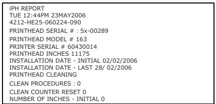
■ iPH REPORT: Displays IntelliSEAQ printhead report data, where:
VIEW: Display data;
PRINT: Print reference label.
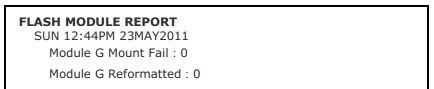
■ FLASH MODULE REPORT: Displays module report data, where:
VIEW: Display data;
PRINT: Print reference label.
IV. Datamax I-4212e Printer Maintenance and Adjustment
4.1 Cleaning the Printhead
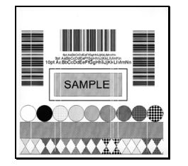
If print quality deteriorates (symptoms include non-standard barcodes, out-of-bounds printing, and striped lines; see sample labels below), a common cause is dirt buildup on the printhead. Furthermore, failing to remove this buildup can lead to component failure and significantly shorten the printhead’s service life.
Steps to clean the printhead:
1. Turn off the printer and unplug the power cord.
2. Open the access cover. Open the printhead locking lever and raise the printhead assembly. Allow the printhead to cool before proceeding.
3. If necessary, separate the label paper and ribbon from the printhead.
4. Use a cotton swab moistened with isopropyl alcohol (do not saturate) to wipe away any dirt buildup on the printhead surface, being careful to control the wetted area. Allow the printhead to dry.
5. Reinstall the ribbon and label paper. Lower the printhead assembly back to the locked position.
6. Close the access cover. Plug in the power cord and turn on the printer. Feed a few labels to normalize information tracking.
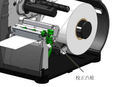
4.2 Label Paper Width Adjustment
When using narrow label paper (smaller than the printhead width), adjust the leveling cam to distribute pressure evenly. The steps to adjust the printhead leveling cam are as follows:
1. After loading the label paper, download the label template (or use the test menu format), and then begin printing a small number of labels.
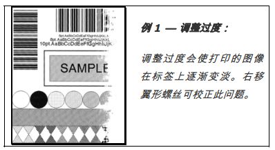
2. While observing the print output, rotate the leveling cam counterclockwise until the image gradually fades on the label, as shown in Example 1.
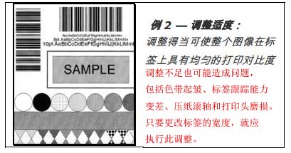
3. While observing the print output, rotate the leveling cam clockwise until the image is fully printed or even shows increased contrast, as shown in Example 2.
4.3 Printhead Pressure Adjustment
Printhead pressure adjustment should be performed after attempting to improve print quality through other print quality controls.
A. After loading label paper, download the label template (or use the test menu format), and then begin printing a small number of labels.
B. Observe the print output, rotating each pressure adjustment screw (using a small coin or screwdriver) by the same amount until the image is fully printed and the contrast becomes uniform:
* Counterclockwise rotation (+) increases the applied pressure;
* Clockwise rotation (-) decreases the applied pressure.
Note: Ensure each arrow points in the same direction.
4.4 Replacing the Printhead
Note: The printhead is fragile, so handle with extreme care and never poke its surface with sharp objects. If you have any questions, contact a qualified technician or MinYong Digital Support before proceeding.
To replace a damaged printhead, follow these steps:
1. Touch any exposed metal parts on the printer housing to discharge any static electricity from your body.
2. Turn off the printer and unplug the power cord. Open the cover; if a ribbon is installed, remove it.
3. With the printhead locked in the down position, loosen the printhead mounting screws (leave them in the printhead assembly).
4. Loosen the printhead assembly. Hold the printhead and lift it. Disconnect both cables and remove the old printhead.
5. Carefully hold the new printhead and connect the two cables.
6. Place the printhead onto the locating pin in the printhead assembly and secure it with the printhead mounting screws (do not overtighten).
7. Clean the printhead (see Section 4.1).
8. Reinstall the ribbon (if it was previously removed), lower the printhead assembly, and rotate the printhead locking lever backward to the locked position.
4.5 Printer Reset
Soft Reset—Steps to reset the printer and clear all temporary host settings:
1. With the printer in the “On” position, press and hold the Pause and Cancel buttons for approximately 4 seconds.
V. Troubleshooting Datamax I-4212e Printer
This section provides information to help users resolve issues when they occur. The table below lists a series of problems that may not necessarily result in an error status.
| question | Solution |
|---|---|
| Unable to communicate via parallel port: | When sending the layout to the printer, observe the “Ready” indicator light. If the light does not flash, check the parallel cable type. Also check the protocol and port settings between the printer and the host computer. |
| Unable to load label paper using the optional cutter: | Warning: Exercise extreme caution. Turn off the printer and unplug the power cord before proceeding. Ensure the cutter is installed correctly. Plug in the power cord and turn on the printer. You should hear the cutter blades rotating and self-adjusting. If the problem persists, call for support. |
| The LCD screen is black, but the ready indicator light is on. | The display contrast setting may be too low. Press and hold the MENU button for 3 seconds, then use the up and down arrow keys to adjust until the display reappears. |
| Uneven paper feeding: | The printer may require calibration; see Section 2.3. |
| The printing is garbled (it prints gibberish instead of the label layout): | The printer may be in hexadecimal dump mode; if serial communication is used, check the host and printer port settings; the printer setting may be eight data bits, while the host setting may be seven data bits (or vice versa). |
| Unable to print Intellifont fonts: | Intellifont format is closely related to Little/Big Endian. Printers use Big Endian. For more information, please consult your font supplier. |
| The printed text on the right side of the label (facing the printer) is faint: | The “Media Width Adjustment” setting may be incorrect; please refer to Section 4.2. The printhead or pressure rollers may be dirty or worn; clean them or call for repair. |
| The printed labels contained incomplete information: | Check the label layout; ensure character positions do not exceed the label size. All row/column values must be large enough to accommodate the characters and barcode. The label layout’s storage requirements may exceed available storage space. Try reducing the storage space allocated to internal modules or the scalar font cache. If using serial communication, ensure the connection cable meets requirements. |
| No printing marks on the left or right side of the label: | The layout may exceed the label size. Please check the label size in your software. For printers with a display screen, also check the values in the Print Control/Column Offset and Print Control/Custom Adjustments/Column Offset menus. |
| No power (all indicator lights are off): | Verify that both the outlet and printer are connected to the AC power cord; also ensure the power switch is in the “ON” position. Verify that the AC outlet is working properly, or try connecting the printer to a different AC circuit. The AC power cord may be damaged; please replace it. The power fuse may be blown; please call a repair service. |
| No content is printed (the label moves forward normally, but no image is printed): | Check the ribbon used to print the image: If there is an image on the ribbon: * Verify that the ribbon is installed correctly. * If installed correctly, the incorrect carbon layer configuration is used. (To check the carbon layer, press the adhesive backing of the label onto the ribbon surface. Only the carbon layer of the ribbon will release ink.) Clean the printhead; then replace the ribbon with the correct type suitable for the printer. If there is no image on the ribbon: Print any internal test labels. If an image is printed, check the printer and host protocol and port settings. Their settings must match. The thermal setting may be too low. Adjust it in the software program or via the menu. The label paper/ribbon combination may be inappropriate. Contact MinYong Digital. The printhead or printhead cable may be loose; turn off the printer and then reconnect it. |
| No action was taken when attempting to print using the software program: | Ensure the printer is ready. Observe the front panel; if the “Ready” indicator light does not flash when sending the layout, check the protocol and port settings between the printer and the host computer. Ensure the connection cable is compatible. |
| Poor print quality: | The printhead may need cleaning; adjust the heat and print speed settings via the front panel or host commands. The label paper/ribbon combination may be incompatible; please contact MinYong Digital. The “Media Width Adjustment” setting may be incorrect; the pressure roller may be dirty or worn; clean the pressure roller or call for service. |
| Labels missing during printing: | A label paper calibration process may be required; the label sensor may be mispositioned; readjust the position; the layout may be less than 1/8 inch from the label’s tail edge. Try reducing the size or slightly moving the layout. |
| Unable to print rotated text: | Character formatting may exceed the label size. Ensure that row/column values provide sufficient space for printing characters or barcodes. See the Programmer’s Manual for details. |